Screw classifier features and working principle
 July.22,2019
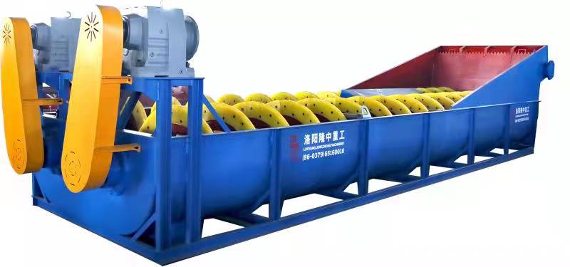
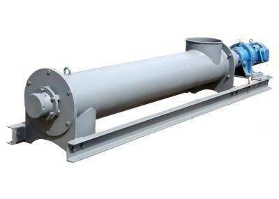
The screw classifier is important grading equipment in ore dressing industry. Often used in ball mills in the concentrator, it is the same with spiral classifier. The main function is to sort out the materials with the required particle size. The structure is mainly composed of a semi-circular water tank, a hollow shaft, a spiral blade, a wear-resistant lining and the like.
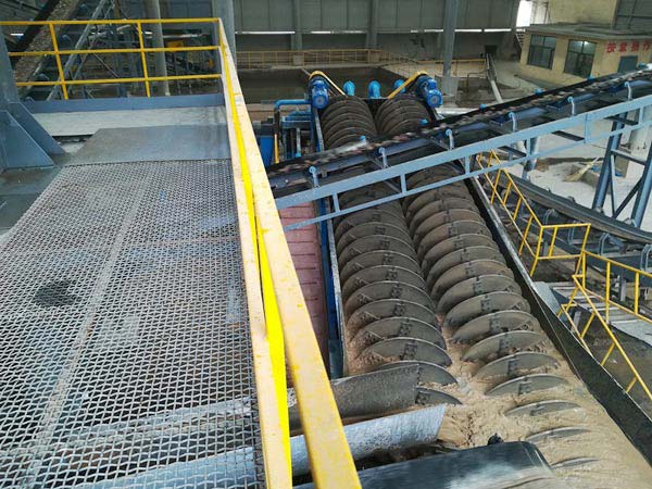
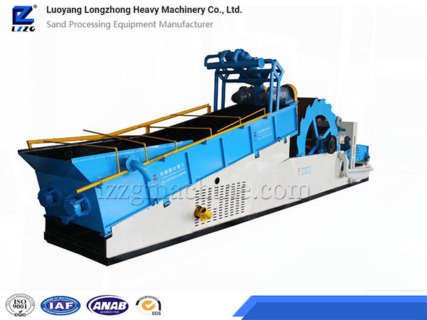
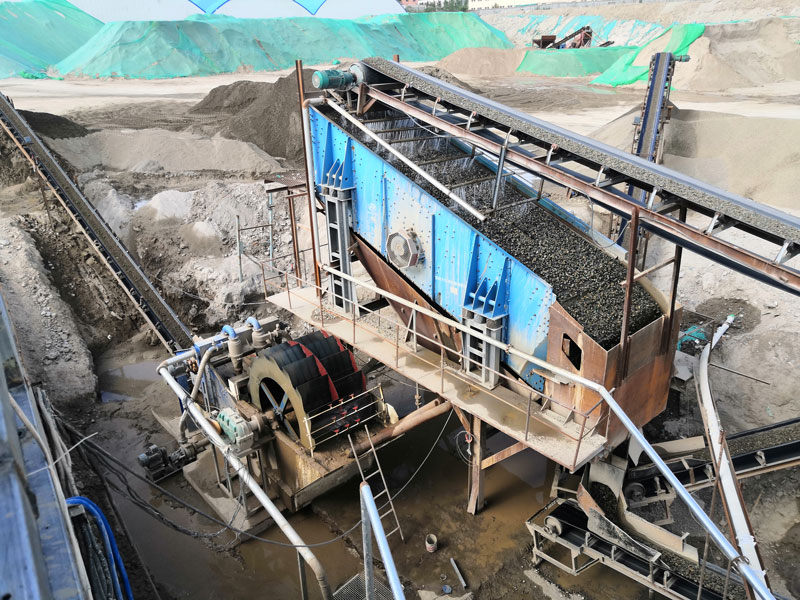
spiral classifier for washing gravel and stone
TYPE OF SCREW CLASSIFIER
The screw classifier is divided into submerged and high weir type according to the structure.
The overflow weir position of the high weir classifier is higher than the center of the bearing at the lower end of the screw shaft but lower than the upper edge of the spiral of the overflow end. It has a certain settlement area, suitable for coarse particle classification, and can obtain overflow particle size larger than 100 mesh.
The entire spiral of the overflow end of the sunken classifier is submerged under the liquid level in the settling zone. The settling zone has a large area and depth. It is suitable for fine particle classification and can obtain an overflow particle size of less than 100 mesh.
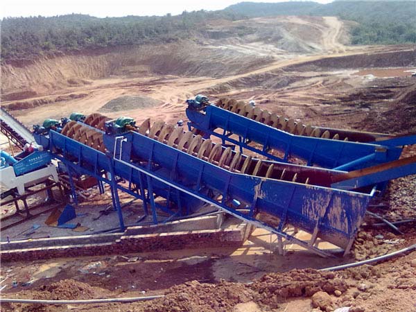
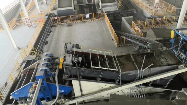
screw classifier in sand washing plant
How the spiral classifier works
The classifier is mainly composed of a transmission device, a spiral body, a trough body, a lifting mechanism, a lower bearing (bearing bush) and a discharge valve.
The water tank of the machine is installed obliquely. The inclination angle is determined according to the equipment configuration in the process flow. The transmission device drives the screw to rotate in the groove. After the fine slurry is fed into the groove from the side feeding inlet, a lower end is formed at the groove. The surface area and volume of the slurry settlement area are determined by the inclination angle of the water tank and the height of the overflow weir. The spiral of low-speed rotation can play a certain agitation. After the slurry is stirred, the light and fine particles are suspended on it to form an overflow, which overflows from the overflow surface of the trough and flows into the next beneficiation process; the heavy particles sink to the bottom of the trough to form a return. The sand is transported by the screw to the discharge port.
Models Parameters Table
| Model | Feed size | Capacity | Spiral diameter | Number of spirals | Tank length | Power | Dimensions |
| mm | t/h | mm | mm | kw | mm | ||
| LX0920 | ≤10 | 30-60 | 920 | 1 | 8000 | 11 | 8710X1630X2080 |
| LX1120 | ≤10 | 40-80 | 1120 | 1 | 8000 | 18.5 | 9230X1840X2130 |
| LX1500 | ≤10 | 50-100 | 1500 | 1 | 8000 | 22 | 9620X2230X2480 |
| 2LX0920 | ≤10 | 60-120 | 920X2 | 2 | 8000 | 11X2 | 8710X2600X2080 |
| 2LX 1120 | ≤10 | 80-160 | 1120X2 | 2 | 8000 | 18.5X2 | 9230X3050X2130 |
| 2LX1500 | ≤10 | 120-250 | 1500X2 | 2 | 8000 | 22X2 | 9620X3730X2480 |


